Steven Engel: Engineering Portfolio
Introduction to Computer Engineering Table of Contents
Course Description
Example Project: LCD Display
LCD Project: Above and Beyond
Other Projects
Final Project
Final Robot in Action
Undergraduate Table of Contents
Main Table of Contents

Introduction to Computer Engineering
Fall 2020, Dr. Roberts
Course Description:
This project-based course introduced several concepts related to computer engineering, electrical engineering, and computer science. This was primarily achieved through self-guided projects using the sparkfun arduino board, since building and analyzing circuits, writing, analyzing, and modifying code, and general engineering skills were needed to succeed. The projects themselves did not take long for me to complete, so I helped my peers to get their circuits working and made special modifications to give the circuits new purposes in my extra time.

Example Project: LCD Display
Many projects were completed in this class, so the LCD (liquid crystal display) project will be used as a model for the types of projects being completed. The goal of this project was to print "Hello, world!" to the LCD, as well as a timer of how long this had been displayed on the second line.
LCD Display Project
First, the circuit was created. Care was taken not to bend the pins on the LCD or potentiometer, and to connect the many pins to the correct ports on the sparkfun board. Then, the code was loaded from a sample code file and modified to display "Hello, world!". Finally, the code was uploaded to the board, the potentiometer was turned so that the characters could be seen, and the following was displayed:

As described, the circuit displays the message "Hello, world!" along with the uptime.
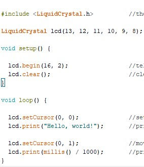
The code being used as instructions to the sparkfun board. The LCD is set up, cleared, then Hello, world! and the uptime are printed on their respective lines.
As described, the circuit displays the message "Hello, world!" along with the uptime.

LCD Project: Above and Beyond
Since the above project took less than ten minutes to complete, after helping my peers to get their circuits working, I decided to modify the behavior of my circuit. Changing the code as shown below, I produced a circuit with the following behavior. First, the LCD is set up. Then, it is cleared, and after a delay of 800ms, "Hello, Steve!" is printed in a random visible location. After 800ms, the LCD is cleared, "Have a good day!" is displayed on the first line for 800ms, and the code repeats.

Other Projects
While the LCD display project was shown as an example, many other projects were completed in this course. This table briefly lists some of these projects, their basic functions, and what extra functionality I added to them.
Project Name | Functionality | Extra Functionality
Blinking LED | Blinks Onboard LED | Blinks onboard and connected LED
Potentiometer | Varies frequency of LED blinking | Varies brightness of LED with Analog pin
Photoresistor | Turns LED on or off based on room brightness | Varies LED brightness with Analog pin
RGB Nightlight | Varies color with potentiometer, brightness with photoresistor| Added more colors
Digital Trumpet | Plays tones based on 3-button input | Plays flats/sharps based on 4-button input
Simon Says Game | Memorization game (must repeat correct pattern using buttons) | Always win
Servo Motor | Controls servo motor position using potentiometer | Controls servo rotation rate
Ultrasonic Distance Sensor | Varies color based on distance from sensor | Added more colors
Motion Alarm | Lights LED, causes servo to rotate based on distance | Plays speaker with distance
Temperature Sensor | Displays temperature in degrees F and C on LCD | Added Kelvin
Headbands Game | Generates names of animals on LCD for players to guess | Changed category
Autonomous Robot | Robot moves forward, then stops and turns before hitting object | Moves faster
Final Project
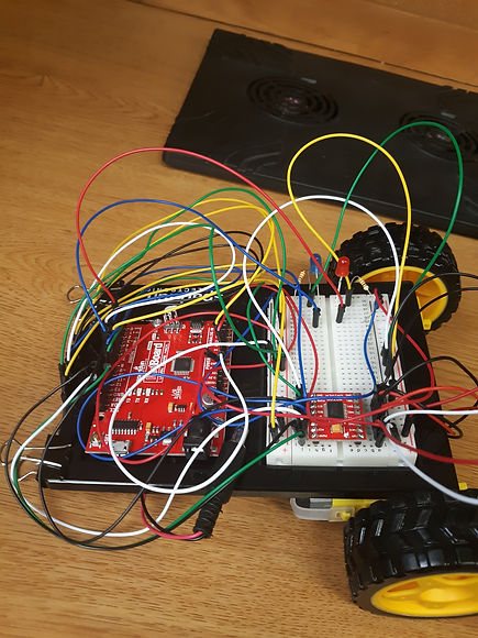
For the final project, a robot was built which followed a black line (marked on the ground with electrical tape). A "line follower" sensor was attached. The robot's left motor would turn the left wheel slightly slower if the robot moved too far right of the line, and the robot's right motor would turn the right wheel slightly slower if the robot moved too far left of the line. This is a picture of the final robot:
Final Robot in Action
This video shows the final robot following a rapidly curving black line. Flashing red and blue LEDs were added for cosmetic effect. Click on the video to play it.