Steven Engel: Engineering Portfolio

Principles of Engineering
2016-2017, Mr. Bernstein and Mr. Cahoon
Course Description:
"Through problems that engage and challenge, students explore a broad range of engineering topics, including mechanisms, the strength of structures and materials, and automation. Students develop skills in problem solving, research, and design while learning strategies for design process documentation, collaboration, and presentation."
https://www.pltw.org/our-programs/pltw-engineering-curriculum#curriculum-2
Principles of Engineering was my first serious engineering course. I learned the basics of several key STEM concepts, but more importantly, I learned how to work in a team and employ the design process in an efficient manner.
Table of Contents

Mechanisms: Compound Machine
This unit introduced equations for calculating Mechanical Advantage for the following Simple Machines:
Lever
Wheel and Axle
Inclined Plane
Pulley
Screw
Wedge
Pulley Drive/Sprocket/Gear Systems
Compound Gear Systems
With this knowledge, students were asked to create a compound machine that could lift 500 grams of weight 12 inches vertically off a table-top. Specifically, the following criteria and constraints were in place:
Criteria:
- Must contain at least 3 simple machines (see above list)
- Can only have human input in one location
- Must fit within a 24” x 24” x 24” space
- Must lift 500 grams 12” off of the table’s surface
Constraints:
- Limited to 3 design and build days
- Can only use Fischertechnik and Vex equipment
The Solution:
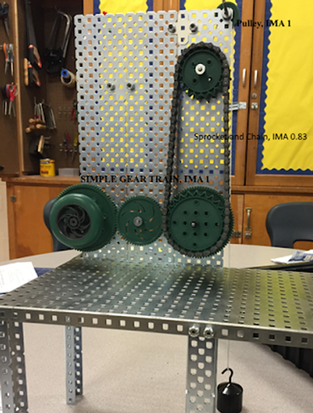
A design was created employing a simple gear chain, chain and sprocket, and pulley. The machine was successful, lifting the 500g weight 12 inches, and falling within the constraints.
This is how the machine functioned:
1. The first wheel was turned by a human hand, which turned a gear on the same axle.
2. This first gear turned a second gear meshed with it.
3. The second gear turned a third gear, on the same axle as the sprocket and chain.
4. A pulley system attached to the sprocket and chain lifted the 500g weight, which was tied to it.
In order to improve the mechanical advantage further, the driven gears should be made larger than the driver gear.

Control Systems
This unit introduced the following topics related to control systems:
Inputs vs. Outputs
Digital vs. Analog
Open vs. Closed Loop Systems
Programming using Robot-C
Building and iterating with VEX robotics equipment.

Control Systems: Robot Challenge
The challenge:
1. Create a Vex robot that will move forward 4 squares (8 feet) from its starting location (from A to B).
2. Have the robot perform a 90 degree turn, then move forward 2 more squares (4 feet, from B to C).
3. Have the robot stop and flash a flashlight 3 times to signal “delivery”
RobotC must be used to program instructions for the robot.
Criteria:
- Robot must complete the above course without error.
- Robot must successfully use encoders to detect when to stop moving.
Constraints:
- Must use Vex equipment to build the physical robot.
- Robot cannot use timers to know when to stop.
Control Systems Challenge: Robot
The robot pictured below was our solution to this challenge. The first image is a side view, while the second image is a top view. The robot completed the challenge successfully, going through the following steps:
The bump switch was pressed.
The motors turned the wheels, moving the robot forward. Meanwhile, the wheels turned a gear which turned the shaft of the quad encoders, which the robot used to correctly determine when to turn and stop.
The robot stopped and flashed the flashlight three times in the correct square.
 Robot Side ViewSide view of the robot. The wheels and encoders can be seen. |  Robot Top ViewTop view of robot. The cortex, bump switch, flashlight, and battery can be seen. |
|---|
Control Systems Challenge: The Code
The code shown below controlled the robot's behavior.
Line-by-line explanation:
Lines 26-27: Resets the quad encoder values to 0, so that the distance would be the same each time the robot was used.
29: Waits until the user presses the bump switch to start the movement of the robot.
30-35: The robot moves straight forward, with a power value of -72 on the right motor and -80 on the left. It does this until an encoder value of 4203 is reached (8 feet). The motors stop.
36-43: The right motor turns forward at a power of -40, and the left motor turns backward at a power of 40, until an encoder value of 520 is reached, or a 90 degree turn to the left. The motors stop.
45-47: The process detailed in 30-33 repeats, only the encoder value needed to stop is decreased to 2200 to signify 4 feet forward instead of 8.
48-61:The motors stop, and the flashlight flashes three times at full power to show that the delivery is complete.

Control Systems: Conclusion
Some components did not respond to programmed instructions as expected. For example, in lines 30-35, when a value of -80 was used for both the left and right motors, the robot veered off course. However, after changing the left motor's value to -72, the robot moved straight forward. Constant iteration happened to make sure that the robot would function correctly. Such iteration is crucial in engineering in order to maximize solution success.