Steven Engel: Engineering Portfolio
Introduction to Engineering Design Table of Contents
Course Description
Brainstorming
Pictorial Sketches
Orthographic Board Drawing
Puzzle Cube Project
Inventor Feature Tools
Parametric Chess Set Project
Hole Table vs. Hole Callout
Tolerance Drawing
Automata Box Project
Reverse Engineering Project
Final Project
Severna Park High School Table of Contents
Main Table of Contents

Introduction to Engineering Design
2017-2018, Mr. Hill
Course Description:
“Students dig deep into the engineering design process, applying math, science, and engineering standards to hands-on projects like designing a new toy or improving an existing product.”
https://www.pltw.org/our-programs/pltw-engineering-curriculum
In Introduction to Engineering Design, I learned that attention to detail and a good work ethic are everything in the world of engineering. I learned the critical skills of sketching, technical drawing, reverse engineering, and project management. I also learned the importance of design as an art and a discipline- creative, yet falling within the criteria and the constraints at the end of the day.
Table of Contents
Brainstorming: Cereal Bowl Challenge
To begin the course, students were asked to make a product with two ordinary white paper cereal bowls. The only criteria? Make it "so that nearly every high school student would want to purchase it."
Criteria:
Design the bowl in a way that “nearly every high school student would want to purchase it”
Constraints:
Can only use:
Two cereal bowls
Colored Markers
Printer Paper
Tape

Solution: The Bowl of Your Dreams
Our group's solution, dubbed "The Bowl of Your Dreams", had the following design aspects:
Tape “latches” to secure the food in the bowl
An ergonomic paper handle to easily carry the bowl
A hinge to easily open and close the bowl.
Conclusion: Creativity and teamwork are important throughout the design process, and are key during the opening stages of any project. The brainstorming stage is critical for all projects, no matter how complex they may be.

Pictorial Sketches
In Introduction to Engineering Design, several weekly sketches were completed to practice visualization and drawing skills, including Isometric Pictorials and Oblique Pictorials. Some of these sketches are displayed below:
Isometric Pictorial: Great War Binoculars
This isometric pictorial sketch shows some binoculars from the Great War.
Notice the attention to detail on the:
Round dial for adjusting the lenses
Much smaller viewing lenses than forward lenses
Relatively rectangular centerpiece

Oblique Pictorial: Salt and Pepper Shaker
This oblique pictorial sketch shows a salt and pepper shaker.
Important Features:
Round dial
Tonal Shading of various parts
Thinner pepper squeezer component
Chamfer and fillet on top
Holes on top
Raised texture on dial and surrounding components


Orthographic Board Drawing
To practice technical drawing, an Orthographic Board Drawing was created. Object, center, and dimensioning lines were used.
Puzzle Cube Project
The Puzzle Cube was the first major engineering project in IED. The Autodesk Inventor program and general design skills were learned during the course of this project.
The criteria were as follows:
2.25”x2.25”x2.25”
composed of 27 cubes
contains at least 6 different colored pieces made of said cubes
The slideshow below contains captioned pictures of the various stages of this project. Left click to view the full images.
 Concept SketchThe original concept sketch, showing how the puzzle cube would look when put together as well as the individual pieces. |  Orange/Brown Piece Orthographic SketchesAfter the initial concept sketch, rough drafts of the orthographic sketches were created for each piece. As shown, they illustrate the top, front, and right view of each piece, thus facilitating the design process in Inventor. |  Orthographic Drawing: White PieceAfter orthographic sketches were completed by hand for each piece, the pieces were created in Autodesk Inventor, and final orthographic drawings were made. The most complicated piece (white) is displayed. |
|---|---|---|
 Assembly DrawingCreated with Autodesk Inventor, this drawing shows the complete cube, the parts involved, and how they come together to make the cube. |  Physical Puzzle CubeFinally, a physical prototype was created using wooden blocks and glue. |
Puzzle Cube Presentation
In order to practice the necessary skill of presenting a finished product, a video presentation was created with Autodesk Inventor. This video shows how the puzzle cube fits together and how the individual pieces rotate from their natural resting positions to form the greater cube. Left click the video to view.
Autodesk Inventor Feature Tools
Throughout the course, several feature tools for advanced modeling were learned and used. The slideshow below displays some of these (left click to view full images with descriptions).
 CoilTakes two perpendicular lines and a circle to form a spring. |  LoftCreates a path between two 2D shapes to form a 3D shape. |  RevolveRevolves a 2D shape around an axis to a specified number of degrees. |
|---|---|---|
 SweepCreates a cylindrical, pipelike structure from a line. |

Parametric Chess Set Project
For the Parametric Chess Set Project, students created chess pieces with a group, following a common theme and adhering to piece-based specifications (for example, the king should be bigger than a pawn, and all pieces should fit within one square on a chessboard).
Parametric Chess Set Project: Famous Buildings
Our group's theme was Famous Buildings. For the queen piece, the Taj Mahal was chosen. Left click on the slideshow below to view the stages of this project.
 Thumbnail SketchFirst, a thumbnail sketch was created to show the concept of the piece. |  Orthographic SketchA sketch of the front, right, and top views of the piece was created. The minarets would later be removed in order to help the piece fit better on a chessboard. |  Orthographic DrawingThe piece was created in Autodesk Inventor, and an orthographic drawing was produced (shown). Advanced feature tools, detail views, and angular, datum, and symmetric dimensioning were used. |
|---|

Parametric Dimensioning
During the Chess Set Project, parametric dimensioning was employed. With this system, all length dimensions of the piece were expressed (directly or indirectly) in terms of one base dimension (30mm, or d0). Therefore, by changing only d0, the entire piece's size could easily be changed.
Hole Table vs. Hole Callout
The hole callout and hole table both give clear instructions to the manufacturer on how to create a hole. For both, a section view is used and projected to an isometric view so that the holes can be easily seen. Left click below to view the details of each.
 Hole TableHole specifications are placed neatly in a table with their x and y dimensions. |  Hole CalloutEach individual hole is given a leader describing the specifications. |
|---|

Tolerance Drawing
Tolerance, in engineering, is the allowance of a dimension on an object to be slightly greater or smaller; in reality, no production line is perfect. A drawing for part “6 -110” was created to simulate this. Shown on the drawing are various ways to indicate tolerance:
Labelling significant digits
Creating reference dimensions
Specifying only an upper or only a lower tolerance
Automata Box Project
An Automata box is an animated decoration utilizing a cam and follower system. This system was simulated in Inventor, using what is known as a driving constraint:
The handle “drives” the angle of the dowel.
This drives the Cam angle.
The follower axle moves up and down along the Cam’s surface.
The decoration atop the follower dowel mimics this behavior.
Each student designed an Automata box unique to their interests. Shown below is an explosion drawing of the parts used to create the box.

Automata Box Design
A model of the automata box was produced in Autodesk Inventor, and a physical prototype was constructed. Click on the videos below to see the automata box in action.


Reverse Engineering Project
For the Reverse Engineering Project, teams of four had to:
Use tools to take apart a product.
Use micrometers and calipers to measure dimensions of product’s parts.
Create manual sketches of parts, observing tolerance, using a proper scale, and calling out fasteners.
Create part files and orthographic drawings in Inventor.
Put all of the parts together in an assembly file for the group so that the product was reassembled in Inventor.
Criteria:
Parts fit together in final assembly
Product chosen displays clear inputs, a function, and outputs
Detailed sketches of product are created
Constraints:
Time (three weeks)
Universal use of Metric vs. Imperial system
Drawings must be to scale
Must require tools to take apart (not too simple)
Reverse Engineering Project: Pencil Sharpener
Each group divided the workload, and created orthographic drawings in order to:
Facilitate the creation process in Inventor
Create needed views (front, top, right, section, and callout)
Learn to work as a team; find strengths of each member
Record necessary dimensions efficiently
The stages of this project are shown below (click below to view them).
 Orthographic SketchThis image shows the front, top, and right views of the inside shaft of the pencil sharpener. Two bolts found with this part are called out as well. Also included is a cross-section view of the inside shaft. |  Inside Mechanism Orthographic DrawingThe parts were created in Inventor, and orthographic drawings with several views were created. This is the inside shaft piece of the pencil sharpener. |  Bolt Orthographic DrawingTwo of these bolts were used as fasteners for the pencil sharpener; they were modeled in Inventor as well. |
|---|---|---|
 Final ProductAll of the parts were successfully represented in Inventor and constrained together to form the pencil sharpener. The covering was left transparent so that the inside could be seen. |

Reverse Engineering: Final Product
The video below shows the pencil sharpener working as intended in Autodesk Inventor.

Final Project
A final project was completed by all students, placed in teams of four. 40 undeveloped problem statements were created by the group until one problem statement was selected and developed with research. The four group members decided on the following problem to tackle:
“There are many intensive activities that water enthusiasts enjoy in the summertime, such as sailing, tubing, wakeboarding, and jet skiing. However, there are many safety concerns associated with them. Approximately 4,600 boating accidents occur every year. Many of these accidents can be attributed to situations when a water enthusiast falls off a boat. In these situations, boats cannot identify people’s location in the water and can run them over and/or crush them with waves.”
Our design statement was to “design, market, test, and create a system that will allow for stranded people in the water to be easily spotted in all water conditions”.
Criteria:
Alerts others to a person’s location in water
Functions in all water conditions
Easy to use for people of all ages
Cost >$15, <$40 as it is just an attachment
Weight < 2.5 lbs so that swimming ability is not inhibited
Constraints:
Completed by 25 May, 2018 (about 1 month)
Safe and environmentally friendly
Should not be an electronic solution
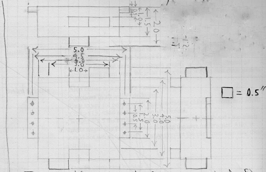
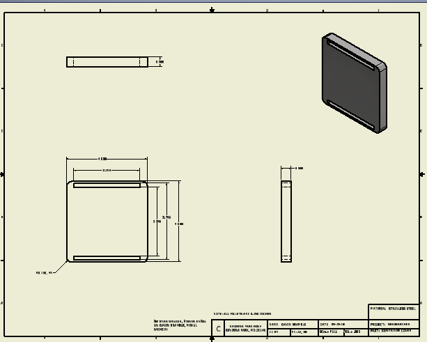
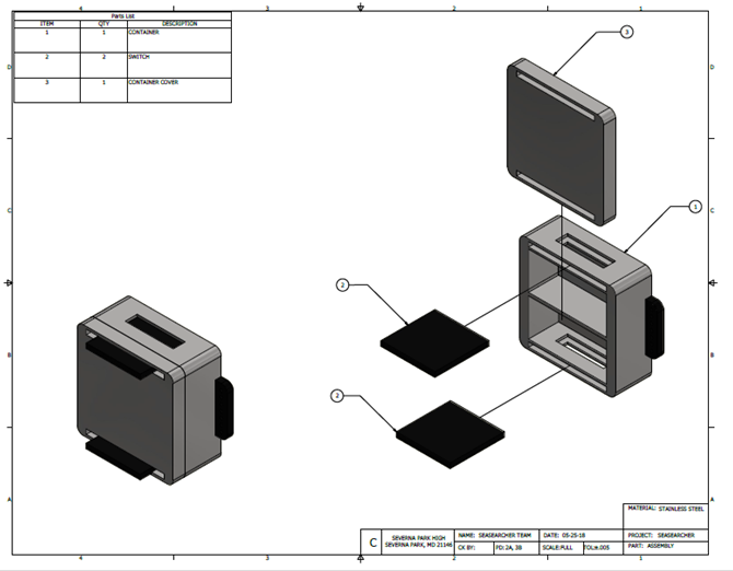
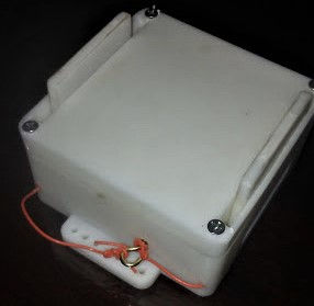
Final Project: "Sea Searcher"
To tackle this problem, our group designed "Sea Searcher", a lightweight PFD attachment which could release smoke into the air or dye into the water if the user pulled a switch. The development of Sea Searcher is shown below (click to view).