Steven Engel: Engineering Portfolio
Engineering Design and Development Table of Contents
Course Description
Introduction
Problem Statement
Problem Interviews
Market Research
Criteria
Initial Ideas
Testing
Solution
Future Iterations
Conclusion
Severna Park High School Table of Contents
Main Table of Contents

Engineering Design and Development
2019-2020, Mr. Cahoon
Course Description:
“The knowledge and skills students acquire throughout PLTW Engineering come together in Engineering Design and Development as they identify an issue and then research, design, and test a solution, ultimately presenting their solution to a panel of engineers. Students apply the professional skills they have developed to document a design process to standards, completing Engineering Design and Development ready to take on any post-secondary program or career.”
https://www.pltw.org/our-programs/pltw-engineering-curriculum#curriculum-9
In Engineering Design and Development, we learned how to work in teams on a year-long project, thereby delving deeper into the professional design process than ever before. Unlike other classes, this class gave us unique experience in that the year-long project was an actual solution to an actual problem, and a unique, real product was developed from scratch.

Introduction
In Engineering Design and Development, we worked in groups to design a solution to a real-world problem, using the engineering design process. Throughout the year, SCRUM and Agile project management strategies were employed to maximize group efficiency, and thereby deliver the best possible solution. Some of these include:
Using Gantt Charts: Gantt charts, long-term visual representations of what needs to be done, were useful in planning general tasks (Product Backlog Items, or PBIs) over long periods of time (several months).
Using Taskboards: Taskboards, physical boards consisting of the general tasks (PBIs) from the Gantt Charts, were useful in planning 3-week periods of time ("Sprints") in which several PBIs would be completed.
Conducting Problem Interviews: Problem Interviews, direct interactions between the group and the general public related to the problem being solved, proved useful in gaining initial knowledge and justification of the problem, as well as allowing us to respond to consumer needs in our design.
Keeping the Minimum Viable Product (MVP) in mind: Understanding the MVP, or minimum the solution has to be in order to solve the problem, helped us to focus on designing the most efficient solution.
Finding the Solution's Unique Value Proposition (UVP): Finding our solution's UVP, or what made it uniquely effective in solving the problem, helped us to focus on what features were most important in the design and to ultimately deliver a marketable product.
Mentors/Company Contacts: Our frequent contact with our mentors, engineers working in the field (Ms. Ricci and Mr. Howard), provided guidance and feedback which would greatly improve our solution. In addition, our contact with various companies (namely, Lee Spring, Husky Inc., Spatco Inc., and Source Fueling and Equipment Solutions) would provide expertise and even critical material donations for the prototype.
Problem Statement
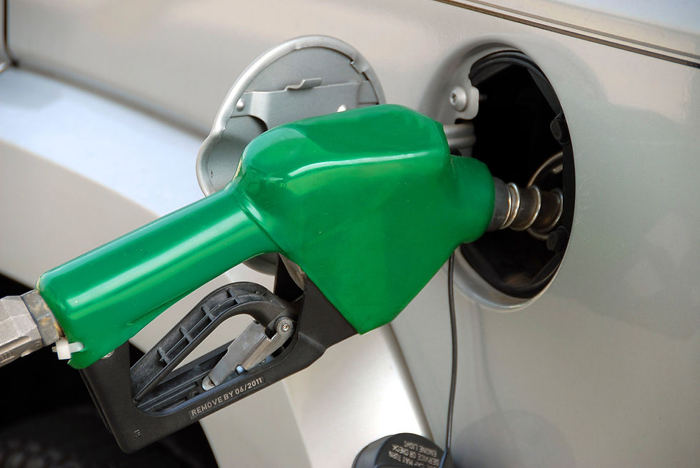
To begin, we formed groups and brainstormed several possible ideas of the form "It would be nice if..." or "I hate it when...". The problem we ultimately decided to tackle was "I hate it when gasoline drips out of the gas nozzle after refueling my car". After doing some research, this idea was formed into a proper problem statement:
"In retail gas pump nozzles (models with automatic shutoff and vapor boot), when the fuel-sensor shutoff hole backfills with gasoline, the vacuum tube experiences an increase in pressure due to the fluid pressure of the gas overtaking the previous pressure of the air, which in turn creates suction in the venturi that collapses the diaphragm, triggering an automatic shut off. However, the excess fuel left in the spout can drip out of the tip, resulting in the loss of approximately 132 million gallons of gasoline per year."
We then learned as much as possible on the subject through problem interviews and market research.

Problem Interviews
Before interviewing, we determined our general target audience- people who pump their own gasoline. Through social media and in-person interviews, we gained the following quantitative data:
35 people were interviewed
14 (40%) were female and 21 (60%) were male
5 (14%) had been driving for more than 35 years
8 (22%) had been driving for more than 5 years
34 (97%) stated that they had experienced the problem of gasoline dripping after refueling
0 (0%) used or knew of a product which solved the problem of gasoline dripping after refueling
In addition, much qualitative data (problem experience, user stories, solution requests) was gained through conversations with the interviewees. This would be used later to guide the development of the solution.
Market Research
In order to understand how the problem was currently solved, we researched several products currently (or, in some cases, previously) on the market. Click on the slideshow below to view some of these products and a summary of their pros and cons.
 No Drip-1“No-Drip 1” mostly (89% of fuel stopped) solves the problem of gasoline dripping out of the nozzle by using pressure differentials and surface tension to keep fuel in the spout. However, this requires a whole new nozzle; this solution is relatively expensive and cannot be retrofit onto current designs. Also, an unintended side effect is that the fuel flow rate is decreased. |  Check Valve DeviceThe Check Valve Device is a spring and cap for the end of the nozzle spout. The spring opens the cap only when the pressure pushing on it from gasoline flowing through the nozzle is sufficient to do so. Otherwise, the cap remains closed, and gasoline generally stays inside the nozzle (not all of the gasoline is stopped 100% of the time, however; this design reduces, but does not eliminate fuel drips). In addition, the tension on the spring must be adjusted for this solution to be compatible with different fuel and nozzle types. |  Garage Oil “Abzorb Mat”The “Garage Oil Abzorb Mat" absorbs liquids, storing them (the capacity is not stated). It is advertised as being for “Under Cars”, but it also works for other applications, like absorbing gasoline. It is a relatively cheap, effective short-term solution. However, it must be discarded/emptied eventually, causing damage to the environment if discarded in a landfill. Thus, it does not really solve the problem in the long-term. |
|---|---|---|
 Oil Absorbent PadsThe Oil and Gas absorbent pad requires users to dispose of it by taking it to a hazardous waste disposal center, an inconvenience for most. However, it provides a simple and effective solution to consumers. The pad can be held under the nozzle as it is removed from the tank and the drips would be absorbed by the pad. Pads can be bought in bulk at a cheap price, as low as $0.45 per pad. However, they are single-use and do not completely eliminate gasoline drips. |
Criteria
Through problem interviews and market research, we found that no current solutions effectively solved the problem. To ensure our own solution's success, we wrote a set of criteria which our solution would be developed from (based on extensive research of current products, patents, industry standards, and federal regulations):
Performance.
Must stop 100% of gasoline from entering the environment; 100% of gasoline should be prevented from entering the environment in the short-term through runoff, and 100% of gasoline should be prevented from entering the environment in the long-term (through absorption into concrete/the ground)
The solution must ensure that the gasoline’s flow rate is between 4 gallons per minute and 10 gallons per minute
Size and Weight.
The outside diameter of the spout (“terminal end”) cannot exceed 0.840 inches
The spout must be at least 2.5 inches long
The retaining spring should terminate at least 3 inches before the end of the spout (“terminal end”)
If the solution is a nozzle or nozzle attachment, the weight of the nozzle should not exceed 4 pounds (approximately one pound more than the standard nozzle weight)
Durability/Operating Environment.
Should be able to operate at temperatures between -60 and 120 degrees Fahrenheit
Should be able to withstand drops from 36 inches onto concrete with no loss in functionality
Should retain functionality in damp and wet situations (90% humidity)
Should be able to last at least 2 years of regular use, or 100,000 cycles, at a retail gas station
Cost.
If the solution is a whole nozzle, it should cost less than $400, retail
Any general consumer products or alternative solutions should not exceed a cost of $0.50 per use or $200 as a one-time cost
Initial Ideas
Based on the above criteria, we developed initial ideas and sketches. Then, through a series of decision matrices, the final idea was chosen: a compressible cover for the gas nozzle. Click on the slideshow below to view this process.
 Collection ContainerOne of the initial ideas was to place a collection container beneath the nozzle so that any excess drips would be collected and later disposed of properly. |  Mechanical LidAnother solution was the mechanical lid; when the user pulled the handle to pump the gasoline, a cap covering the end of the spout would open. When the user (or automatic shutoff) released the handle, the lid would close, stopping further drips. |  Electronic Sensor/LidA similar solution was the electronic sensor and lid. When it was detected that the handle was pulled and gasoline was flowing through the nozzle, the lid would open; otherwise, the lid would close, stopping any drips. |
|---|---|---|
 compressiblecover.pngAnother solution, the compressible cover, would be modeled after a play tunnel or accordion folding. If the user pressed the nozzle against the gas tank, the cover would retract, allowing fuel to flow freely into the gas tank. However, when the user pulled the nozzle out of the gas tank, the cover would expand back to its original length, covering the spout and stopping any drips. |  Initial Weighted Decision MatrixFrom these ideas (and several others) a weighted decision matrix was produced. Each idea was discussed by the group and scored on a 1-5 scale on how well it met each criteria. From this, it was determined that the compressible cover was the idea which met the criteria best. |  Final Weighted Decision MatrixFinally, each group member sketched and/or described their specific vision of how the compressible cover would be designed (or what components it would include). From this, it was determined that an attachable, compressible cover with a collection container would be designed. |
Testing and Design
The compressible cover was then designed in Autodesk Inventor, and a prototype was constructed. During this time, various test procedures were written and conducted in order to hold the solution to the original criteria and to guide its development.
Test Procedures
Materials Test
The materials test was conducted so that the materials selected for the design would meet the most design criteria. Extensive research was completed for how various candidate materials (organic cotton, silicone, polyester, high-impact polystyrene, and ABS plastic, among others) stood up to the design criteria. In the end, a decision matrix similar to the ones used for the initial ideas was used to select the materials used:
High-Impact polystyrene was used for the non-compressible parts of the design due to its high stength, low weight, low cost, and ability to be injection molded. Polyester was used for the compressible section of the design due to its high flexibility, high strength, low weight, and low cost.
Spring Test
In order to make the cover compress, a compression spring was employed in the design; thus, a spring test was needed in order to determine and test the optimal specifications for the spring.
First, measurements were taken to determine that the ideal spring would be 5 inches long and would compress by 3.5 inches under a typical force when refueling at the gas station (roughly 6 Newtons). Then, using Hooke's Law (F=kx), the ideal spring constant was calculated. Finally, three springs of varying spring constants (60, 75, and 90N/m) were placed under 6 Newtons of weight and observed.
The 60N/m spring was selected for the design since it was the only spring that successfully compressed by 3.5 inches when placed under 6 Newtons of weight.
Durability Test
Once the prototype was completed, the durability test was needed in order to make sure that the device was not too fragile. Specifically, the device was dropped 36 inches onto concrete from various positions (upside-down, rightside-up, on its side).
The device showed no visible signs of damage except for minor scrapes to the outside layer. There was no loss in functionality.
Other Tests
Various other tests were completed during the design phase, such as the following:
Size Test
Weight Test
Gas Collection Test
Each test aided in the development of the solution and helped it to meet the initial design criteria.
The Solution: ZeroDrip
The solution, named ZeroDrip, consists of various parts. Click on the slideshow below to view ZeroDrip's design and the prototype that was constructed.
 Lower Base PieceFirst, the lower base piece is slid onto the end of the nozzle. It contains a special valve and threads on the bottom to allow the collection container to screw on. |  Upper Base PieceThe upper base piece is then interlocked with the lower base piece, forming a solid base cover. |  Complete Base PieceThe base piece is finished by sliding two rods through the interlocked holes. |
|---|---|---|
 Compressible Cover PieceThe compressible cover has a connection piece with threads which screws onto the base piece. This piece has sewing holes which the spring and polyester are sewn to, forming a cover. |  Cap PieceFinally, a cap piece is sewn to the other end of this cover. Made of rubber, these flaps form an opening and closing cap based on pressure applied to the nozzle. Here the cap is shown just as the nozzle spout is pushing it open. |  SolutionPut together, these parts make ZeroDrip, as shown. The cover compresses, allowing gas to flow into the tank when refueling. The cover then expands back to its original length, stopping any drips. Then, when the nozzle is hung back up after refueling, any drips caught within the device flow down into the collection container. |

Future Iterations
Of course, any solution can continue to be modified and improved. Also, a solution is not always just a physical product. These are some options we would consider in the future:
Oleophobic Coating: Oleophobic coating repels oils and gasoline, causing them to "slide off" of any surfaces. If the inside of the nozzle spout and/or device had oleophobic coating, gasoline would easily flow where it belongs: in the vehicle tank or collection container.
Large-scale Production Methods: While 3D printing and hand-sewing were used to make the prototype shown above, injection molding and machine-based sewing would be more appropriate for large-scale production.
Government Incentives: In order to improve the appeal of the product to gas station owners, we would contact local congressmen and work with them to form a bill calling for subsides for the purchase of our product/similar products or a federal regulation mandating the product/similar products.
Engineering Design and Development: Conclusion
Since this class was entirely project-based, many skills were learned from pure experience, including but not limited to the following:
Teamwork and responsibility in engineering
Project Management (with SCRUM/Agile)
Time Management (with Gantt Charts/Taskboards)
Interview Skills (from Problem Interviews)
Research Skills
Technical Writing (from Test Procedures and various other documents)
Professional Communication (with group members, mentors, and companies)
Understanding overall systems (from initial ideas)
Visual conceptualization and sketching
Design objectivity and professionalism
Advanced Autodesk Inventor/CAD Design Skills
Technical Drawing (with Autodesk Inventor)
3D printing and hand sewing (from prototype construction)
Government knowledge (from Government Incentives plan)
Presentation Skills (from final presentation)
These important skills would be useful in preparing me for the future as an aspiring engineer.